EDEM File Types
| File | Type | Description |
| .DEM | Data file | Simulation data file for each simulation and exported particle. This contains information about the custom properties used in the simulation. |
| .dfg | Config file | Configuration information for the simulation. This contains the Simulator and Analyst settings. |
| .h5 | Simulation h5 data file | HDF5 files containing simulation data. Located in a sub-folder based on simulation name. |
| .dll | Library | EDEM uses dll Library files for contact models, particle body forces, and user-defined factories. Use Tools > Options > File Locations to change dll. |
| .ess | Data file |
Binary file that stores per-simulation data for selections. Note: If .ess file size exceeds ~ 4.3 GB EDEM displays a warning “detected corruption in settings file…” upon opening due to a data structure size limitation. |
| .efd | Field Data file | File containing the field data information. This now supports files larger than 4GB. .edf files are written in HDF5 format. |
| materialsDB.h5 | Materials database h5 data file | The materials database is used to define any material used in a model. The user can transfer any material to and from a simulation (including shape and interactions) to a HDF5 file format. Use Tools > Options > File Locations to change its location. |
| .ptf | Particle template | The particle template file contains mesh information. It is created whenever you save a model containing a particle template. |
| .gddb | GEMM database file | File containing all the material information from the EDEM GEMM database. |
EDEM Standard Supported File types
| File Extension | Type | Source Software Application |
|
.3dm |
Geometry |
Rhino |
|
.case |
Data |
EnSight |
|
.CATPart .CATProduct .model |
Geometry |
CATIA v4/v5 |
|
.csv |
Data |
Any spreadsheet or other software application that can read text files. |
|
.iam .ipt |
Geometry |
Inventor |
|
.igs .iges |
Geometry |
IGES |
|
.jt |
Geometry |
Intergraph JT |
|
.msh |
Geometry |
FLUENT Mesh |
|
.obj |
Geometry |
OBJ |
|
.sat .sab |
Geometry |
ACIS |
|
.sldprt .sldasm |
Geometry |
Solid Works |
|
.stl |
Geometry |
STL |
|
.stmod |
Geometry |
Inspire |
|
.stp .step |
Geometry |
STEP |
|
.x_t .xmt .txt .x_b |
Geometry |
Parasolid |
|
.prt |
Geometry |
NX file |
|
.prt .asm .g |
Geometry |
Pro/E |
EDEM Optional Supported File types
| File | Type | Source Software Application |
|
.cgns |
Data* |
CFD software applications that can read the generic CFD General Notation System format. For example, FLUENT, CFX, and STAR-CD. |
*Enabled with the Field Data Coupling Module.
Estimating Simulation Time
Exact estimation of the real time required for a DEM simulation is challenging, as each simulation and each computer is different. However, see below for some general advice on estimating Simulation Time.
Time Step
One of the key numbers in DEM simulation is the Rayleigh Time Step. This is the time taken for a shear wave to propagate through a solid particle. It is therefore a theoretical maximum Time Step for a DEM simulation of a quasi-static particulate collection in which the Coordination Number (total number of contacts per particle) for each particle remains above 1. It is given by:

where R is the particle’s radius, ρ its density, G the Shear Modulus and v the Poisson’s ratio. This formula assumes that the relative velocity between contacting particles is very small. Other than for quasi-static systems, in practice some fraction of this maximum value is used, and for high coordination numbers (4 and above) a typical Time Step of 0.2TR (20%) has been shown to be appropriate. For lower coordination numbers, 0.4TR (40%) is more suitable.
Hertzian Contact
Whilst the Rayleigh Time Step is a suitable starting point for quasi-static simulations, for systems undergoing flow it may be that a shorter Time Step is required. Consider two elements approaching each other at a speed v. In one Time Step, t, the maximum possible overlap is:
![]()
In DEM, particles undergoing elastic (Hertzian) contact are treated as overlapping and this overlap is equated to a surface compression. t in the above equation must be such that the maximum overlap is lower than the theoretical maximum overlap for Hertzian contact. In practice, to get a good numerical integral to the contact graph at least six time points should occur (though ten is more desirable) - three during approach and three during separation.
Elastic Impact
From Hertz theory of elastic collision the total time of contact is given by:

Where:

Where mi and mj are the mass of the two elements.

Where Ri and Rj are the radii of the two elements.

where νi and νj are the Poisson’s ratio of the two materials.
![]()
Where Vz is the relative velocity and Vi and Vj are the velocity of the two elements.
Attribute Definitions
Particle Attributes
| Attribute | Description |
|
Angular Velocity |
Angular velocity is defined as the speed at which an Object rotates. |
|
Charge |
Charge is an electrical property of particles (such as electrons and protons) which causes them to attract and repel each other. A material with an excess of electrons has a negative charge; material with an absence of electrons (or an excess of protons) has a positive charge. Materials with a balanced number of electrons and protons are called 'neutral'. Positive and negative charges attract each other. |
|
Compressive Force |
The compressive force is the sum of the surface normal force magnitudes.
|
|
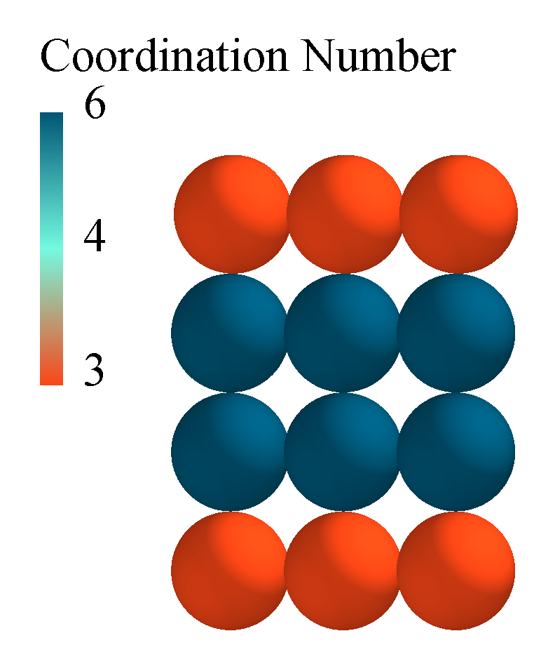
The Coordination Number of a particle is the number of contacts that a particle has with the spheres of another particle at any given point in time.
Below is an image of a 3-sphere particle shape. Four particles are placed on top of each other. The base and top particles have a Coordination Number of 3 as each particle is in contact with 3-spheres of the middle particles. The middle two particles have a Coordination Number of 6 as they are in contact with 3 spheres of the particle above and 3 spheres of the particle below.
The particle-geometry contacts are not counted in the Coordination Number.
|
|
|
Diameter |
Diameter of the particle (based on the largest X, Y or Z component of the bounding box around the particle). |
|
Distance |
Distance is defined as how far apart the center of a particle is from a reference point or plane. |
|
Electrostatic Force |
Electrostatic force is a force of interaction between charged particles, measured in Newtons. In EDEM the force is calculated using the screened Coulomb force equation. |
|
ID |
A Geometry element, particle surface, particle and collision all have unique ID numbers. |
|
Moment of Inertia |
Inertia is a measure of a particles resistance to a change of momentum. For a sphere:
|
|
Kinetic Energy. |
The kinetic energy is defined by:
where v is the velocity magnitude of the particle. |
|
Mass |
The mass of a particle is defined as the magnitude of the gravitational force on a particle.
|
|
Number of Particles. |
The number of particles is the total number of particles in a simulation (or bin group) at that point in time. In a bin group the option of “total over time” can be used. This will produce a cumulative particle count for any particles that pass through that bin group. Please note that the total over time option can only be used for bin groups with 1 bin. |
|
Orientation |
Orientation is the alignment of a particle in relation to Cartesian space. It is represented in EDEM as a 3-by-3 matrix that defines the rotation of the particle from its original orientation (as defined in the Creator and assigned an identity matrix). |
|
Position |
The x, y, or z position of the center of the particle. |
|
Potential Energy. |
The potential energy is defined by:
where m is the particle mass, g is gravity and h is the distance between the center of mass of the particle and the defined “ground” level. If gravity is acting in negative Z the ground level is z=0. |
|
Residence Time. |
Residence time is a measure of how much time a particle has existed in the simulation. “Residence time = Simulation Time - Particle Creation Time”. Note that if the Analyst > File > Export Simulation Deck functionality is used you have the option to Set Simulation Time. If used this option will influence the Residence Time shown on the particles following the above equation. |
|
Rotational Kinetic Energy. |
The rotational kinetic energy is defined as:
where I is Inertia and ω is the angular velocity magnitude. |
|
Time |
In EDEM time is the real time it takes for an event to occur. |
|
Torque |
The torque on the particles is defined as the tangential contact force * particle radius. |
|
Total Energy. |
The total energy of a particle is the sum of the kinetic energy, rotational kinetic energy and potential energy of a particle. |
|
Total Force. |
The total force is the resultant unbalanced forces on a particle or Geometry element in x y and z. |
|
Velocity |
The velocity of the particles is defined as the rate of change of displacement (in x, y and z). |
|
Voidage |
Voidage is the percentage of space not taken up by particles. Voidage can be obtained by creating a Grid Bin and creating a Voidage query. The Voidage property is calculated as:
Where Vbin is the volume of the defined bin, and Vparticle is the sum of the volume of all the particles inside the bin. Voidage therefore does not consider the overlap between particles, which this quantifies the deformation of the particles. A particle which overlaps two or more bins will only be counted in the bin that contains the particle center of mass. |
|
Volume |
The volume of a particle is defined as the amount of space that it takes up. |


Geometry Attributes
| Attribute | Description |
|
Charge |
Charge is an electrical property of geometries (such as electrons and protons). A material with an excess of electrons has a negative charge; material with an absence of electrons (or an excess of protons) has a positive charge. Materials with a balanced number of electrons and protons are called 'neutral'. Positive and negative charges cause an attractive force to be applied between the elements (particle-geometry). |
|
Compressive force |
Sum of the surface normal forces on the geometry. |
|
Distance |
Distance is defined as how far apart the center of a geometry node is from a reference point or plane. |
|
Electrostatic force |
Electrostatic force is a force of interaction between charged elements, measured in Newtons. In EDEM the force is calculated using the screened Coulomb force equation. |
|
ID |
A geometry element, particle surface, particle and collision all have unique ID numbers. |
|
Node 1, 2, 3 |
The position (x, y and z) of the geometry nodes. |
|
Number of geometry elements |
Geometries are split into triangular elements. The number of geometry elements is a summation of this. |
|
Position |
The X, Y, or Z position of the center of the geometry element. |
|
Torque |
The torque on the geometry is defined as the tangential contact force * distance where the distance is the distance from the center of mass to the contact point.
The torque is calculated from the individual torque and moment about each individual geometry element. This is then converted to the torque on the whole geometry about the center of mass. The torque can be plotted/exported along the x, y and z axis. |
|
Total force |
The total force is the resultant unbalanced forces on a particle or geometry element in x y and z. |
|
Velocity |
The velocity of the geometry is defined as the rate of change of displacement of the individual geometry nodes. |

Contact Attributes
| Attribute | Description |
|
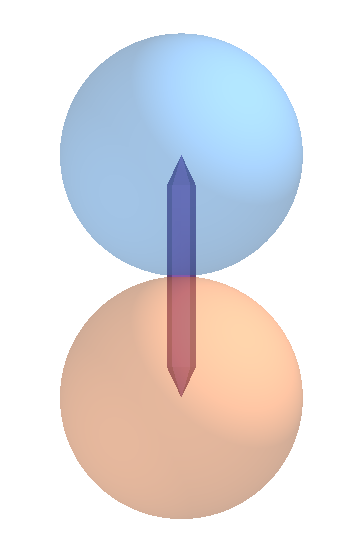
Contact vector 1,2 |
When two particles collide the contact vector is the vector connecting the contact point to the center of the particle.
|
|
Distance |
The distance from the point of contact to a user-defined point or plane. |
|
Normal force |
The normal force arises when two bodies are in direct contact with one another. It always acts perpendicular to the body that applies the force. The force depends on the contact model used, typically this will be a spring force with damping component. The reported force on particles includes damping forces, the reported force on geometries is the undamped force.
|
|
Normal overlap |
The normal overlap represents the normal deformation of a particle. The normal overlap N between two particles i and j at positions pi and pj with radii ri and rj is defined as:
|
|
Number of contacts |
Contacts are the impacts occurring between elements at data write-out points. In other words, the contact is in progress when the write-out takes place. The contact has an associated force, position and so on - these are discrete values. If two elements stay in contact with each other for some time e.g. over four write-out points, four contacts will be stored and each of these may have a different force, position and so on. |
|
Position |
The central point between two elements at the point in time when a contact starts. |
|
Tangential force |
The tangential force is the force from the tangential overlap.
|
|
Tangential overlap |
The tangential displacement of the contact point up to the point at which the contact ends or the particle begins to roll or slip. The tangential overlap represents the tangential deformation of a particle. |
|
Time |
In EDEM time is defined as the real time it takes for an event to occur. |

Collision Attributes
| Attribute | Description |
|
Average normal force |
The average normal force over the duration of a single collision. |
|
Average tangential force |
The average tangential force over the duration of a single collision. |
|
Distance |
Defined as the distance from the collision position to a user defined point or plane. |
|
Duration |
Collision duration is the total time that the two elements involved in a collision are in contact. |
|
End time |
The end time is the time at which the collision ends. |
|
ID |
Each collision has a unique number which can be used to track the unique collision and the elements involved. |
|
ID Element n |
Each element in a collision has a unique number. |
|
Maximum normal force |
The maximum normal force experienced during a single collision. |
|
Maximum tangential force |
The maximum tangential force experienced during a collision. |
|
Normal energy loss |
The energy lost during a collision due to the normal overlap. |
|
Number of collisions |
The number of completed collisions. Only completed collisions are counted: collisions in progress (contacts) are not counted. |
|
Position |
The central point between two elements at the point in time when a collision starts. The collision position is written out on completion of the collision. |
|
Relative velocity |
Relative velocity of two elements in a collision is Va - Vb Note: This value is calculated from the contact points and not the particle centers. |
|
Relative velocity normal |
Relative normal velocity of two elements in a collision is Vna - Vnb |
|
Relative velocity tangential |
Relative tangential velocity of two elements in a collision is Vta - Vtb |
|
Start time |
Defined as the point in time when the first contact of a collision occurs. |
|
Tangential energy loss |
Energy lost during a collision due to the tangential overlap. |
|
Time |
In EDEM, time is defined as the real time it takes for an event to occur. |
|
Total energy loss |
The sum of the normal and tangential energy loss. |
|
Velocity of element A/B |
The velocity magnitude of an element involved in a collision, element A will have the lowest ID number and element B will have the highest. |
Bonding Attributes
| Attribute | Description |
|
End Time |
The point at which a bond breaks. |
|
Normal Force |
The resultant normal force experienced by the bond. |
|
Normal Moment |
The normal moment applied to the center of the cylindrical bond. |
|
Number of Broken Bonds |
The total number of broken bonds in the simulation. |
|
Number of Intact Bonds |
The total number of intact bonds in the simulation. |
|
Start Time |
The point in time at which the bond was created. |
|
Tangential Force |
The resultant tangential force experienced by the bond. |
|
Tangential Moment |
The tangential moment applied to the center of the cylindrical bond. |
Using EDEM Remotely
Typically, EDEM users set up simulations on Windows. However, the simulation is run on a Windows or Linux processing machine which is not in your location.
You can set up a simulation on a local machine and copy to a Windows or Linux machine and run in Batch mode, this doesn’t require the user interface. See the help section Running EDEM in Batch Mode for further details.
However, if your requirement is to use the EDEM Graphical User Interface (GUI) to access the Creator, Simulator or Analyst when working on a remote computer typically two different options are used. Windows Remote Desktop and VNC for Windows or Linux.
Particle Display Options
The Particle Display options can be accessed at EDEM > Tools > Options >.
-
Legacy Particle Display. Uses the legacy display for everything. This will be forced when Modern OpenGL is not available.
-
Sphere Particle Display Legacy. Legacy display for default particles (spheres). Not recommended as it's the slowest. Needed for when Modern OpenGL is not available.
-
Sphere Particle Display Standard. Same as the previous default particle display.
-
Sphere Particle Display Instanced. New instanced implementation for default particles. Improves performance for Nvidia video cards.
-
Use Legacy polyhedral particle display. Toggles between legacy and instanced polyhedral particle display. By default using instanced.
-
Use Legacy Spherocylinder display. Toggles between legacy and instanced Sphero-Cylinder particle display. By default using instanced.
-
Use Legacy cone particle display. Toggles between legacy and instanced cone particle display. By default using instanced.
-
Use legacy vector particle display. Toggles between legacy and instanced vector particle display. By default using instanced.
-
Use legacy stream particle display. Toggles between legacy and instanced stream particle display. By default using instanced.
-
Use legacy template particle display. Toggles between legacy and instanced template display. By default using instanced (when default particles are also instanced). Forced to use legacy when using the standard, non-instanced default particle
-
Reduce new template details during camera movement. When using the instanced templates, this option will allow you to reduce the template details during camera movement if they wish, using default particles and speeding up the rendering.
-
Use legacy contact display. Toggles between legacy and instanced contact particle display. By default using instanced.
-
Use legacy geometry display. Toggles between legacy and instanced geometry particle display. By default using instanced.
-
Use legacy geometry transparency display. Toggles between legacy and instanced geometry transparency display. By default using instanced. Using the legacy display is likely to render elements in the incorrect order so geometries may appear in front or behind objects when they should not.
Particle Display Options
If this option is checked then EDEM will use a legacy Method for displaying particles. If it is not checked then EDEM will make more use of the graphics card on the processing machine, this can improve the speed of displaying particles, especially for large amounts of material (1 million + particles).
Testing on a Windows processing machine with Nvidia GTX 970 graphics card shows that with legacy particle display on Remote Desktop the frame rate is around 10 fps and using Turbo VNC without legacy display the frame rate for EDEM is 50 fps.
Displaying particles is 15x-25x faster without legacy particle display however there is no change in the speed of reading data, as a result creating videos and playing through a simulation (1 million particles and ½ million particle simulations tested) is 20%-30% faster on Turbo VNC as animation speed is a combination of reading data and displaying data.
This option cannot be used by default when using Remote Desktop, the slower legacy display option has to be used, the section below provides details of a workaround for both VNC and Remote Desktop.
Using Remote Desktop
Remote desktop is installed on most Windows operating systems. To use please see the link below:
The advantage of using Remote Desktop with EDEM is that you can use all the local computers programs, files and network resources. One disadvantage of Remote Desktop is that it disables the graphics card on the processing machine and uses its own video driver to display the output. Described by Microsoft as:
“On the server, RDP uses its own video driver to render display output by constructing the rendering information into network packets by using RDP protocol and sending them over the network to the client. On the client, RDP receives rendering data and interprets the packets into corresponding Microsoft Windows graphics device interface (GDI) API calls”
This means that advanced features of EDEM designed to help speed up the display of large simulations (millions of particles) are also disabled and results in slow graphical performance when using Remote Desktop. You can check if the advanced graphical features are active in EDEM by going to Tools > Options > Particle Display.
If ‘legacy particle display’ is selected then EDEM is not using the processing machines graphics card effectively to display the particles, when using Remote Desktop the following message will be displayed if this option is not disabled:
In order to use the Advanced OpenGL features on Remote Desktop user has to do the following:
- Go to Start and type “View Running processes with Task Manager”.
- In the Task Manager window go to Users.
- RDP session for ‘user’ will be shown. Make note of the ID.
- Create a windows batch (.bat) file and open this with a text editor and add in the following:
tscon ID /dest:console
start "" "C:\Program Files\Altair\2022.1\EDEM\bin"
- ID should be replaced with the ID of the RDP session. Save and close.
- Run the .bat file as administrator.
This batch file closes the Remote Desktop session and opens EDEM in a form that allows the Advanced OpenGL features to be used. Logon to remote desktop again and EDEM will be open, go to Tools > Options > Particle Display and ensure ‘legacy particle display’ is not checked.
Using Turbo VNC and Tight VNC
VNC (Virtual Network Computing) is an alternative to Remote Desktop. This comes with a Client to be installed on your machine and a Server to be installed on the processing machine, this can be a Windows or Linux processing machine. Typically, this requires administrator privileges to setup.
Typically, EDEM Engineers use Tight VNC for the server on the processing machine and Turbo VNC for user machine. The advantage of using Turbo VNC is that the advanced graphics card options can be used (de-select ‘legacy particle display' from EDEM Tools > Options > particle display).
Users should refer to the Turbo VCN and Tight VNC documentation for installation and use:
http://www.turbovnc.org/ - Turbo VNC website.
https://sourceforge.net/projects/turbovnc/files/ - Turbo VNC Download Page.
http://www.tightvnc.com/download.php - Tight VNC website and Download link.
It is recommended to reduce the Screen polling cycle for the Server to 30 ms (allows EDEM to display at 30 frames per second) for improved visualization speed, the default 1000 ms polling cycle resulted in slow EDEM display speeds.
VNC on Linux
On Linux VirtualGL and TurboVNC support remote OpenGL rendering which is required by EDEM. This requires VirtualGL to be installed, see the following link for more details:
To use...
- SSH to the machine first (using putty for example) and start the VNC server (under your user account:
/opt/TurboVNC/bin/vncserver
- After the server starts take note of the number at the end of the line starting New ‘X’ desktop (see below) then you can exit putty.
- From your own machine start the VNC client and enter the FQDN of the machine followed by a colon and the number you took note of previously.
- After clicking connect you will next get the following authentication screen looking for your password. After entering you password you should be presented your whole desktop as if you were at the console
- To use edem you must run it using the following command
/opt/VirtualGL/bin/vglrun edem
- When you are finished SSH back into the machine and stop the VNC Server
/opt/TurboVNC/bin/vncserver -kill :1 <replace 1 with the number from step 2>
Coupling Interface Programming Guide
Custom Particle Property Unit Types
| Unit Type | Identifier | SI Units |
| Other | 0 | Unknown unit |
| None | 1 | Unitless |
| Acceleration | 2 | m/s2 |
| Angle | 3 | Rad |
| Angular Acceleration | 4 | rad/s2 |
| Angular Velocity | 5 | rad/s |
| Density | 6 | kg/m |
| Energy | 7 | J |
| Work Function | 8 | J |
| Force | 9 | N |
| Charge | 10 | C |
| Length | 11 | m |
| Mass | 12 | kg |
| Moment of Inertia | 13 | kg/m2 |
| Shear Modulus | 14 | Pa |
| Time | 15 | s |
| Torque | 16 | Nm |
| Velocity | 17 | m/s |
| Volume | 18 | m3 |
| Frequency | 19 | Hz |
| Temperature | 20 | K |
| Heat Flux | 21 | W |
| Stiffness | 22 | N/m |
| Stress | 23 | Pa |
| Mass Flow | 24 | kg/s |
| Stiffness per Unit Area | 25 | N/m3 |